Using 20×4 RGB LCD over i2c with a Raspberry Pi
Now there’s a specialist blog post title if ever there were one…
Recently, I’ve been dabbling with electronics to fill the void of spare time I’ve found myself with while I’m between jobs. I’m currently working on a half-baked idea to create some sort of digital assistant who will take instructions in some form, and then read stuff back to me in a Siri-esque manner. Nothing sounds more awesome than having twitter @replies read out to you, right?! To kick off this project, and get me motivated to actually do something, I ordered a boatload of parts from Adafruit, and set about learning how to use them. First challenge – connecting up their 20×4 RGB backlight negative LCD screen to my Raspberry Pi.
In order to assist with this, I also bought the i2c / SPI character LCD backpack in order to save some GPIO pins for other uses. Due to my lack of attention while ordering, I failed to notice that the LCD backpack only has 16 pins, whereas the LCD screen I ordered has 18 (2 more for the extra background LEDs). Rather than giving up and being limited to only a single channel of control for the backlights, I decided to connect pins 14 to 18 direct into the Pi, and mash two separate libraries together to give myself full control. This is what I ended up with (click for big):
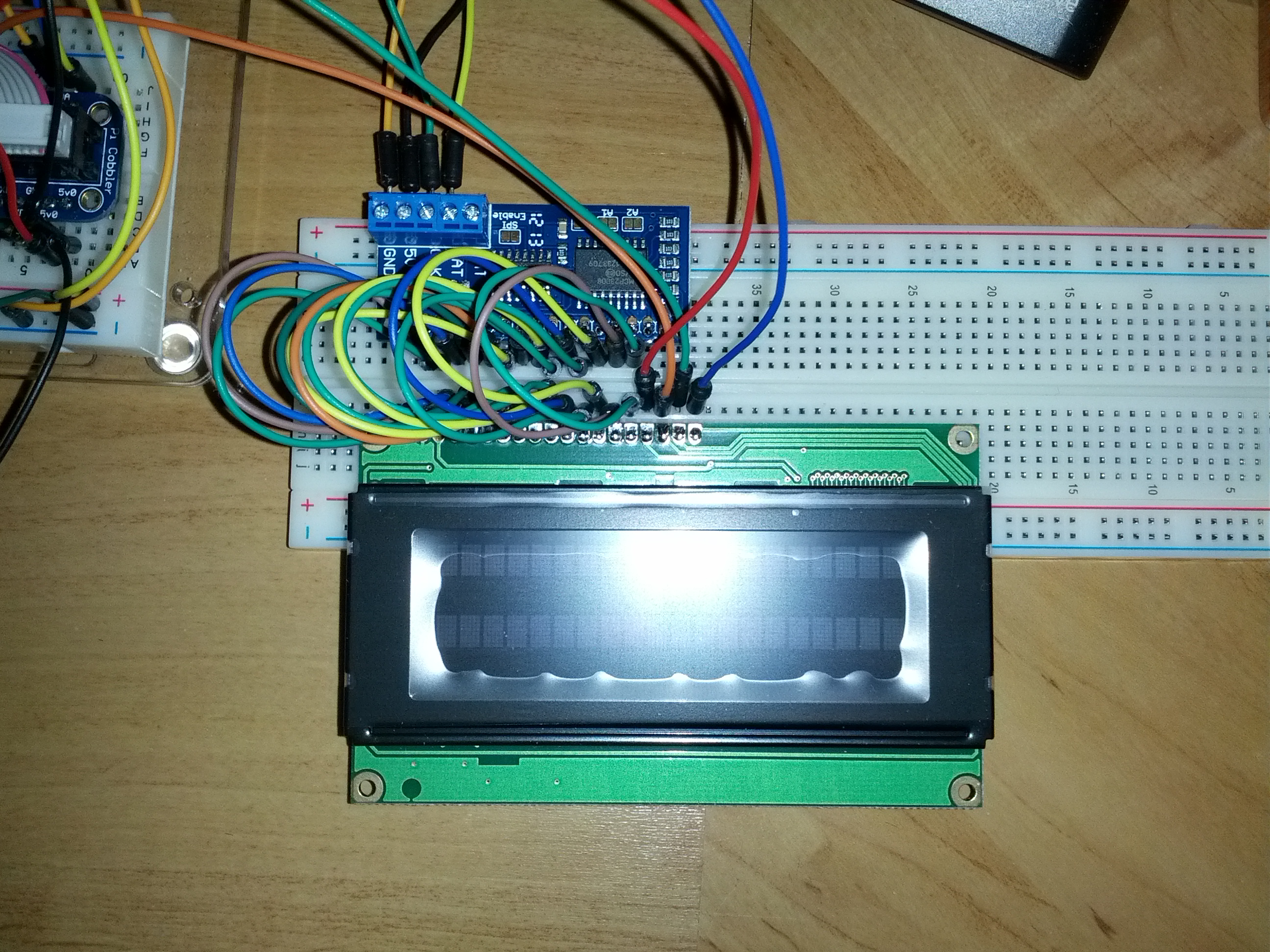
Now, that looks like an absolute mess. That’s because it is. In an attempt to make that a bit more readable, here’s a Fritzing diagram of how it’s wired (again, click for big).
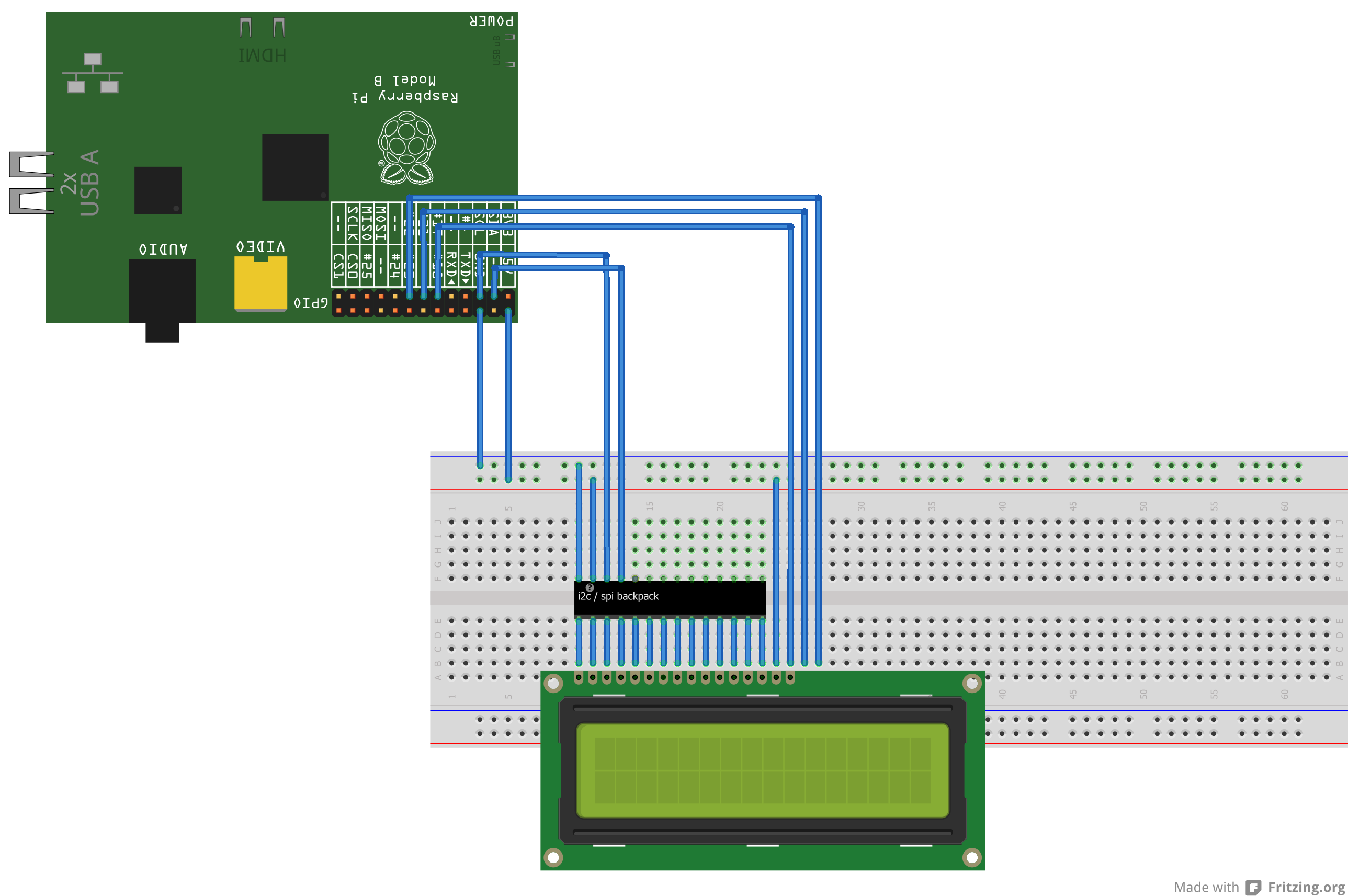
Now, that’s even more confusing as I couldn’t find a Fritzing library with the right parts – so I’ve fudged a few things. Imagine there are ports 17 and 18 on the LCD, and that the LCD itself is 20×4 rather than 16×2. Secondly, imagine the chip in the middle is actually the i2c backpack mentioned above, so everything on the bottom is connected straight to ports 1 to 16 on the LCD, and the VCC/GND/CLK/DAT are connected to the Pi. So, in terms of wiring we get:
- LCD #1 to #14 -> i2c backpack #1 to #14
- LCD #15 -> 5V0
- LCD #16 -> Raspberry Pi GPIO 17
- LCD #17 -> Raspberry Pi GPIO 27
- LCD #18 -> Raspberry Pi GPIO 22
- i2c backpack GND -> GND
- i2c backpack VCC -> 5V0
- i2c backpack CLK -> Raspberry Pi SCL
- i2c backpack DAT -> Raspberry Pi SDA
Now that’s all set up, you can use the standard AdafruitLcd Python library (nice adaptation that I used can be found here) to control the text shown on screen, but we need something bespoke for our background lighting. For future projects, I wanted the ability to control each colour individually, so I can set arbitrary RGB values on the screen, and also brighten/dim appropriately. The latest version of RPi.GPIO will let you do software Pulse Width Modulation, which will achieve this quite nicely for us. To install the latest version (0.5.2a at the time of writing), you’ll need to run the following on your Pi (as root):
$ wget https://pypi.python.org/packages/source/R/RPi.GPIO/RPi.GPIO-0.5.2a.tar.gz
$ tar xf RPi.GPIO-0.5.2a.tar.gz
$ cd RPi.GPIO-0.5.2a
$ python setup.py install
So, combining some standard example code for PWM on the Pi with the AdafruitLcd library, I developed my own little library for controlling a LCD wired up in this manner. To get up and running with the code I wrote, you will need (again, as root):
$ mkdir lcdtest
$ cd lcdtest
$ svn co http://projects.mattdyson.org/projects/LCDControl@889 .
$ git clone https://github.com/PDKK/RpiLcdBackpack.git
$ touch RpiLcdBackpack/__init__.py
$ python testLCD.py
Note: If you see IOError: [Errno 5] Input/output error when running testLCD.py, you may need to edit RpiLcdBackpack/RpiLcdBackpack.py and change the line self.__bus=smbus.SMBus(0) to self.__bus=smbus.SMBus(1). This should only happen on newer versions of the Pi, where the i2c bus number changed to 1 from 0.
Note 2 (added 15/10/14): The version of my LCDControl library that you’re checking out with the above command is now out-dated, I’ve updated the library to use pigpio instead of RPi.GPIO, as the latter was causing me flickering problems when the Pi was under load. To get the latest version, remove the @889 from the svn co command, you will need to have pigpio installed and running for this to work.
Once you run testLCD.py, you should see the screen flash a series of colours, followed by some messages appearing on the screen. Yaaay – it works!
The LCDControl class I’ve written is pretty basic (I’m still learning Python… slowly!) but allows you to set RGB or individual colour values for the backlights, and also pass in any message without worrying about formatting. Currently (version 1.0 at the time of writing), the LCDControl.setMessage method will split by the newline character (\n) and do the logic regarding line numbers for you (as the third display line on the LCD is actually carried over from the first line passed to the controller, and the fourth with the second) – future iterations of this code will allow you to do things such as full text wrapping, and scrolling text.
So there we have it – a 20×4 RGB LCD screen talking to a Raspberry Pi over i2c, retaining individual control over the background LEDs. As always, please leave a comment if you spot anything wrong with what I’ve written here, or have any feedback/suggestions/requests!